
 |
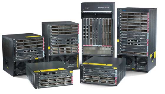
| Cisco Catalyst |
Type the letters LAN into Google and pretty near the top of the list is the Wikipedia definition of a LAN: ‘A local area network (LAN) is a computer network covering a local area, like a home, office, or group of buildings’. But what actually goes into this network? What is the significance of the OSI seven-layer model? What is the OSI seven-layer model? If you have been wondering what the components of a LAN are but perhaps have been afraid to ask, this article is for you. Maren Bennette explains. |
So what is the OSI 7-layer model then? And why is it important? Let’s answer the second question first. Without a well defined, standards-based model for communications between different computerbased systems, there would be IT chaos. Imagine a world where one manufacture’s PC couldn’t send or receive mail from another manufacturer’s PC. In which web sites could only be accessed by people with a certain web browser, but not others. This is why the Open Systems Interconnection 7-layer model for networking, developed by the International Standards Organization in the late 1970s, is so important. The model defines seven layers arranged in a stack as shown in the diagram below. This diagram is unusual in that it shows the 7-layers from left to right rather than top to bottom as is the norm, but we have chosen to use it because it provides a great deal more information than most.
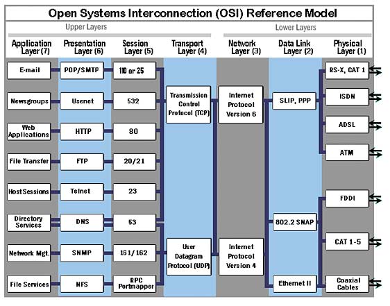
Okay, but what about TCP/IP, then? As well as having an understanding of the OSI 7 layer model, it is also important to know how the TCP/IP suite of protocols maps to the OSI model. It is the combination of these two models that form the basis for all IP networking today. The TCP/IP protocol stack is a group of protocols that all work together to allow software or hardware to perform a function. It uses four layers that map to the OSI model as follows:
• Layer 1: Network Interface - This layer maps to the Physical and Data layers (1 and 2) of OSI and routes the data between devices on the same network. It also manages the exchange of data between the network and other devices.
• Layer 2: Internet - This layer corresponds to the Network layer (OSI’s layer 3). The Internet Protocol (IP) uses the IP address, consisting of a Network Identifier and a Host Identifier, to determine the address of the device it is communicating with.
• Layer 3: Transport - Corresponding to the OSI Transport layer (layer 4), this is the part of the protocol stack where the Transport Control Protocol (TCP) can be found. TCP works by asking another device on the network if it is willing to accept information from the local device.
• Layer 4: Application - Layer 4 combines the Session, Presentation and Application layers of the OSI model (layers 5 to 7). Protocols for specific functions such as email (Simple Mail Transfer Protocol, SMTP) and file transfer (File Transfer Protocol, FTP) reside at this level.
Source: www.thisishowstuffworks.com
Now I understand the TCP/IP 4 layer and OSI 7-layer models, but where do bridges, hubs, routers and switches fit in? When IT manufacturers first wanted to connect peripherals such as terminals and printers to their mainframe computers, they used many different forms of communications links, including serial and parallel cabling. None of these methods was very efficient and wouldn’t scale up to meet the growing demand for connectivity. This became even more of a problem with the advent of the PC. Now there were hundreds of devices that needed to be linked together, which would in time become thousands in larger installations.
Thus the need for local area networks came about. A lot of smart people at places like Stanford University, Xerox’s Palo Alto Research Centre (PARC) came up with the myriad technologies that form the basis of local area networking. As is the way of all technological development, entrepreneurs exploited the research to develop products that made it all work. These included the various types of cabling systems, repeaters, hubs, bridges, routers and last but not least, LAN switches.
But as in all technological developments since the wheel was invented and some smart Egyptian who said “should we put spokes on it?” came along, there have been the ‘religious’ battles. Which is better: hubs or switches? Should different LAN segments be connected with bridges or routers? Which company makes the best widgets? After many years of struggle, the market has more or less made its mind up. Switches are better than hubs. And routers are better than bridges. As to which company makes the best products, our LAN switching review in April’s edition might help answer that question…
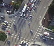 |
collision increases significantly. But wouldn’t it be amazing if you could take an exit ramp from any one of those roads to the road of your choosing? That is exactly what a switch does for network traffic. A switch is like a cloverleaf intersection — each car can take an exit ramp to get to its destination without having to stop and wait for other traffic to go by.
A vital difference between a hub and a switch is that all the nodes connected to a hub share the bandwidth among themselves, while a device connected to a switch port has the full bandwidth all to itself. For example, if 10 nodes are communicating using a hub on a 10-Mbps network, then each node may only get a portion of the 10 Mbps if other nodes on the hub want to communicate as well. But with a switch, each node could possibly communicate at the full 10 Mbps. Think about our road analogy. If all of the traffic is coming to a common intersection, then each car has to share that intersection with every other car. But a cloverleaf allows all of the traffic to continue at full speed from one road to the next.’
Fine, but when it comes to bridges and routers, why do routers come out on top? Here we turn to www.wikipedia.com: ‘Bridging and Routing are both ways of performing data control, but work through different methods. Bridging takes place at OSI Model Layer 2 (Data- Link Layer) while Routing takes place at the OSI Model Layer 3 (Network Layer). This difference means that a bridge directs frames according to hardware assigned MAC addresses while a router makes its decisions according to arbitrarily assigned IP Addresses. As a result of this, bridges are not concerned with and are unable to distinguish networks while routers can.
When designing a network, you can choose to put multiple segments into one bridged network or to divide it into different networks interconnected by routers. If a host is physically moved from one network area to another in a routed network, it has to get a new IP address; if this system is moved within a bridged network, it doesn’t have to reconfigure anything.’
In reality, routers won the technology battle with bridges, for the simple reason that there are now so many different LAN networks supporting myriad devices, even within a single company, that bridges would never be able to handle all the traffic. When the Internet is brought into the picture, the need for routers is even more obvious: the Internet is nothing more than a network of networks, all using IP as the network layer protocol. No routers, no Internet.
Okay, but what’s the difference between a switch and a router then? Back to www.howstuffworks.com: ‘You can see that a switch has the potential to radically change the way connected devices communicate with each other. But you may be wondering what makes a switch different from a router. Switches usually work at Layer 2 (Data Link) of the OSI Reference Model, using MAC addresses, while routers work at Layer 3 (Network) using IP addresses. The algorithm that LAN switches use to decide how to forward packets is different from the algorithms used by routers to forward packets.
One of these differences in the algorithms between switches and routers is how broadcasts are handled. On any network, the concept of a broadcast packet is vital to the operability of a network. Whenever a device needs to send out information but doesn’t know who it should send it to, it sends out a broadcast. For example, every time a new computer or other device comes on to the network, it sends out a broadcast packet to announce its presence. The other nodes (such as a domain server) can add the computer to their browser list (kind of like an address directory) and communicate directly with that computer from that point on. Broadcasts are used any time a device needs to make an announcement to the rest of the network or is unsure of who the recipient of the information should be.
A hub or a switch will pass along any broadcast packets they receive to all the other segments in the broadcast domain, but a router will not. Think about our four-way intersection again: All of the traffic passed through the intersection no matter where it was going. Now imagine that this intersection is at an international border. To pass through the intersection, you must provide the border guard with the specific address that you are going to. If you don’t have a specific destination, then the guard will not let you pass. A router works like this. Without the specific address of another device, it will not let the data packet through. This is a good thing for keeping networks separate from each other, but not so good when you want to talk between different parts of the same network. This is where switches come in.’
Just to confuse matters, it is possible to buy a layer 3 switch. So what’s the difference between a layer 3 switch and a router? A Layer 3 switch is a high-performance device for network routing. Layer 3 switches actually differ very little from routers. A Layer 3 switch can support the same routing protocols as network routers do. Both inspect incoming packets and make dynamic routing decisions based on the source and destination IP addresses inside.
Layer 3 switches were conceived as a technology to improve on the performance of routers used in large LANs like corporate networks. The key difference between Layer 3 switches and routers lies in the hardware technology used to build the unit. The hardware inside a Layer 3 switch merges that of traditional switches and routers, replacing some of a router’s software logic with hardware to offer better performance in some situations.
And it is also possible to buy switching products that work at layers 4 to 7. What do they do? Here we turn to Nortel for an explanation: Layers 4-7 switching refers to software and hardware-based management of application, Internet/intranet traffic based on attributes found at or above the protocol layer of the IP packet. The ability to read information deeper into the IP packet than Layer 2/3 switches/routers can enable intelligent services such as application acceleration, content-aware and user-aware load balancing, application redirection, and advanced application security.
Layer 4-7 switches can read application-level information in packet headers - such as what type of user or device is requesting the content (handheld device, frequent shopper, first-time visitor, etc.), or payloads such as what type of content the user is requesting (application type, application data, executable script, static content, streaming Webcast, shopping cart, etc.).
This information enables the switch to intelligently distribute requests to the most suitable application server, based on geographic location, latency, application or server load, or other factors that would be unknown to Layer 2/3 routers and switches. Layer 4-7 switches also work in harmony with content caches, security devices, and other purpose-specific components to extend application/content awareness and traffic-management intelligence to a complete application and content distribution network.
Network Design
Now you know about bridges and routers, hubs and switches. You know why you would choose one device over another. But how do you bolt them all together? This is where each end-user, each manufacturer of networking equipment, each service provider, systems integrator and reseller and (often enough) each individual network designer would have their own ideas about which way the network should be designed.
Some would opt for a flat, single tier LAN switching network. Others would argue for a 2- tier network made up of an access tier and a backbone tier. Yet more would suggest a 3-tier network, sandwiching a distribution tier between the access and backbone tiers. To our mind there is no one ‘right’ design philosophy. It will depend on how many servers, PCs, printers and WAN links there are, what connection speeds are wanted, the types of applications to be supported and last but not least, how much money is available.
But there are some basic do’s and don’t of network design, especially when the network is going to carry voice and (perhaps) video, as well as data. Here they are:
First, use LAN switches throughout. Don’t be tempted to uses hubs. They won’t work. The choice is then between layer 2 and layer 3 switches. Often layer 2 switches can be used throughout. Sometimes a layer 3 switch is used as a backbone switch (thus creating a 2 tier network). This is a decision for the techies to make, depending on the design parameters for the network.
Second, ensure that the LAN switches support 10/100-megabit Ethernet at the very minimum. Even though VoIP requires relatively low bandwidth, do not be tempted to use cheap 10- megabit switches to keep the price down. Whilst they may do the job today they certainly won’t when the attached devices (PCs, printers, phones, etc) are upgraded, as they will be in time. And if video is going to come into the picture, the faster the LAN switch the better! For the backbone tier, give serious consideration to using Gigabit Ethernet switches. For most users 10/100-switches will probably do the job at all network tiers, but for ‘power’ users (such as media and design companies, and those using applications such as data mining or e-learning) it is best to use 10/100/1000-megabit switches in the distribution and backbone tiers.
Thirdly, the LAN switches must comply with the appropriate standards. For Quality of Service these would include DiffServ, RSVP and 802.1pq. Putting in a LAN switch that doesn’t support Quality of Service means that the managing director’s telephone call will be competing with all the other applications on the network, which is not good. The 802.3af Power over Ethernet standard is also important. Whilst it is possible to buy IP phones that take their power from an AC wall socket, it is much better to have the network supply the power, as it is far neater and probably cheaper in the long run.
Last but not least, make the LAN reliable by using multiple links between the edge switches and those at the centre. Consider using Uninterruptible Power Supplies to keep the LAN switches up in the case of a power failure. At the core of the network, use switches that have built-in resiliency. The additional cost of reliability will be more than paid for in user satisfaction levels, especially if the network is carrying voice traffic. People don’t mind too much if they can’t get their email or surf the web. They do mind if they can’t make telephone calls.
So there you have it. Should you want to know more, the author offers via Comms Business Magazine a half day ‘Networking 101’ training course which covers the basics of LANs and WANs.
Glossary:
• Bridge – an internetworking device connecting two or more network segments or subnetworks at the Data Link layer (2). A bridge uses the MAC (q.v.) address to forward or filter network traffic allowing only essential network traffic to cross the bridge.
• Cat x cabling – various physical cabling standards. There are 6 types at the time of writing, e.g. Cat 5, the cabling type used for 100-Mbps Ethernet LANs.
• Hub – a hub is a device for connecting multiple twisted pair or fiber optic Ethernet devices together, making them act as a single segment. Hubs work at the physical layer (1) of the OSI model. Hubs are either active or passive. Active hubs repeat the signal received at one port out each of the other ports (but not the original one). The device is thus a form of multiport repeater. Ethernet hubs are also responsible for forwarding a jam signal to all ports if it detects a collision.
• Local Area Network (LAN) - A LAN is a network of computers that are in the same general physical location, usually within a building or a campus. If the computers are far apart (such as across town or in different cities), then a Wide Area Network (WAN) is typically used, though these days it is possible to get LAN Extension Service from various service providers.
• LAN Switch – a LAN switch is a device similar to a hub, in that it provides a central connection between two or more computers on a network, but with some intelligence. (A switch operates on Layer 2 (or above) of the OSI 7-layer model and a hub operates at Layer 1.) Whereas for a hub any message received at the hub is broadcast to all the attached computers, with a switch it is sent only to the destination computer and is not visible to other attached devices. This does not prevent ‘broadcast’ messages from being sent to all attached devices.
• Media Access Control (MAC) address - This is the unique physical address of any device (such as the NIC in a computer) on the network. The MAC address, which is made up of two equal parts, is 6 bytes long. The first 3 bytes identify the company that made the NIC. The second 3 bytes are the serial number of the NIC itself. A Layer 2 LAN switch uses MAC addresses to direct network traffic. A Layer 3 LAN switch uses both MAC addresses and IP addresses.
• Network Interface Card (NIC) - Every computer (and most other devices) is connected to a network through an NIC. In most desktop computers, this is an Ethernet card (normally 10 or 100 Mbps) that is plugged into a slot on the computer’s motherboard.
• Router - A router is a computer networking device that forwards data packets across a network toward their destinations, through a process known as routing. Routing occurs at Layer 3 (the network layer) of the OSI 7-layer protocol stack.
• Segment - A segment is any portion of a network that is separated, by a switch, bridge or router, from other parts of the network.
• TCP/IP – The TCP/IP architectural model has 4 layers that approximately match 6 of the 7 layers of the OSI reference model. The TCP/IP model does not address the physical layer, which is where the basic network hardware devices (hubs, repeaters, cabling, WAN, etc.) reside. The network layer, the Internet layer, the transport layer and the host to host layer equate to OSI layers 2 to 4. The TCP/IP application layers are matched by the Session (layer 5), presentation (layer 6) and application layer 7 in OSI.
• V-LAN Virtual LAN - is a method of creating independent logical networks within a physical network. Several VLANs can co-exist within such a network. This helps in reducing the broadcast domain and administratively separating logical segments of LAN (like company departments) which should not exchange data using LAN (they still can by routing).
Sources: http://computer.howstuffworks.com; http://en.wikipedia.org; http://www.thecma.com; www.tcpipguide.com